This page provides practical data and tips relating to Synovatron products.
Please
feel free to ask questions or make suggestions for support info in the
comments section at the bottom of this page; let me know what you need!!
Support information on this page
- Downloadable document links
- Front panel design and module placement
- DIY1 and DIY2 prototype board layouts
- Ribbon cable info
- Wiring hints and tips
Downloadable PDF Documents.
User
manuals, data packs and fitting instructions have now
been rehosted onto Google Docs where they can be viewed or downloaded.
The links are shown below, they may get updated with new revisions and
additions from time to time so please check back here for the latest
info.
Euro Module User Manuals
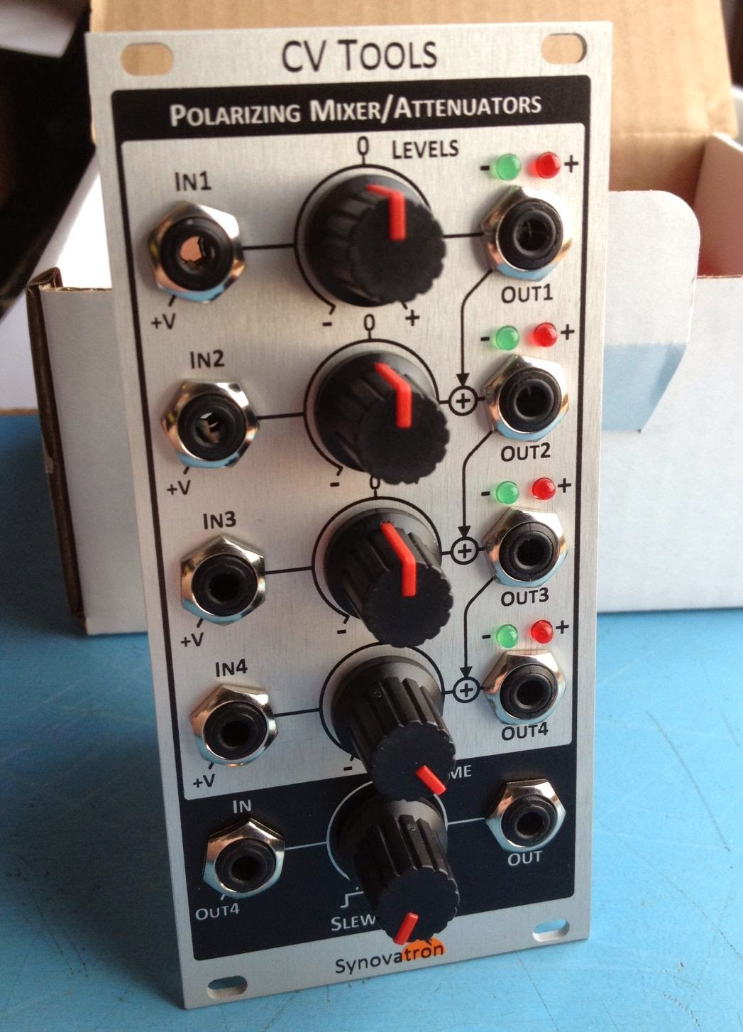
CV Tools: User Manual Rev 1.5 Oct 2011Cascade Polarising Mixer/Attenuator/Slew
https://drive.google.com/file/d/0B8AeYUlWxvI2NkNDRm9SdE1UdGs/view?usp=sharing
CVGT1: User Manual Rev 1.3 Nov 2014 (Serial Numbers 101-548)
Euro to Buchla CV/Gate/Trigger/Pulse Translator
https://drive.google.com/file/d/0B8AeYUlWxvI2cmFhOGR0bWtYR0k/view?usp=sharing
CVGT1: User Manual Rev 1.4 Jul 2017 (Serial Numbers 549 onwards)
Euro to Buchla CV/Gate/Trigger/Pulse Translator
https://drive.google.com/open?id=0B8AeYUlWxvI2YUlvLW9qX1h0VG8

ModuleModule User Manual
cvgtMM: User Manual Rev 0 Feb 2014
Buchla to Euro/serge CV/Gate/Trigger/Pulse Translator
https://drive.google.com/file/d/0B8AeYUlWxvI2bkl0VmpHRUhjMVU/view?usp=sharing

cvgtElements Data Packs
GTPulse: Data Pack Rev 1.1 June 2015 *UPDATED*
Gate/Trigger to Buchla Pulse Translator
https://drive.google.com/file/d/0B8AeYUlWxvI2Q2Y5akFndzhPbnc/view?usp=sharing

CV1.2: Data Pack Rev 0 June 2015 *NEW*
Euro 1V/octave CV to Buchla 1.2V/octave CV Translator
https://drive.google.com/file/d/0B8AeYUlWxvI2YVZBa1NqR2hrZHM/view?usp=sharing

Analogue Systems to Doepfer (Euro) Adaptors Instructions
ASM2DB Adaptor:Fitting Instructions
Analogue Systems Module to Doepfer Bus Adaptor
https://drive.google.com/file/d/0B8AeYUlWxvI2TlI4VHhlV3lEcW8/view?usp=sharing
uZeus Tech Note
If using an ASM2DB Adaptor on a uZeus ribbon cable bus then read this to avoid damaging a module - DO NOT line up the red stripes
https://drive.google.com/file/d/0B8AeYUlWxvI2XzNnNFY3SnFmWkU/view?usp=sharing

DM2ASB Adaptor: Fitting Instructions Rev 2 Oct 2012
Doepfer Module to Analogue Systems Bus Adaptor fitting instructions
https://drive.google.com/file/d/0B8AeYUlWxvI2cHNfdTZYSU9TYk0/view?usp=sharing

5ASM2DB Adaptor/Expander: PCB/Kit Data Sheet & Fitting Instructions Rev 0.1 2014
5 channel Analogue Systems Module to Doepfer Bus Adaptor Board fitting instructions and bare board info for DIYers
https://drive.google.com/file/d/0B8AeYUlWxvI2TWFLMk1uTkRFSEk/view?usp=sharing

STEMCELL Module Kit Details and Project Instructions

STEMCELL 4HP Multi-option DIY Kit: STEMCELL basic kit Overview Rev 0 May 2014
Overview of the basic STEMCELL kit showing PCB layout and schematic.
https://drive.google.com/file/d/0B8AeYUlWxvI2ZzhDLWJLcHJtX00/view?usp=sharing
STEMCELL 4HP Multi-option DIY Kit: STEMCELL kit Passive Multiples Project Rev 0 May 2014
Project description and assembly details for four possible Passive Multiples projects using just the STEMCELL basic kit.
https://drive.google.com/file/d/0B8AeYUlWxvI2MVh3ZFEwYkFnTzQ/view?usp=sharing
STEMCELL 4HP Multi-option DIY Kit: STEMCELL kit Diode (Gate/Trigger) Combiner Project Rev 0 May 2014
Project description and assembly details for a Diode Combiner project using the STEMCELL basic kit and just a few components.
https://drive.google.com/file/d/0B8AeYUlWxvI2b2RsNzN5VWxLdmM/view?usp=sharing
STEMCELL 4HP Multi-option DIY Kit: STEMCELL kit Trunk-Lines Project Rev 0 May 2014
Project description and assembly details for a Trunk-Lines project using two or more STEMCELL basic kits, a few connectors and some ribbon cable.
https://drive.google.com/file/d/0B8AeYUlWxvI2dzFtVUloWWZjSWc/view?usp=sharing
Front panel design and module placement.
 |
| Two panel configurations that can accomodate DIY kits |
Tone's top tip: When
mounting DIY2 closely on the left of DIY1 (i.e. 20mm hole centres) crop
the centre (wiper) pins of the pots close to the PCB - there is a very
small clearance but this will ensure they don't touch or short out on
the jack sockets; If you fit DPDT switches in place of any jacks then
you must crop the the pots as described as the switches are taller than
the jacks.
DIY Prototype Board Layouts.
The
following diagrams show the connectivity of standard components such as
pots and jacks, the tracking to show which pads are connected and some
ideas for mounting LEDS and switches. The fainter images are useful for
planning your component layout. If you want higher res images please
request them on this e-mail link.


Ribbon Cable Info.

Wiring Hints and Tips
Kynar wire is my recommendation
for wiring the DIY boards. It's a very thin single strand wire made of a
0·25 mm diameter (30 a.w.g.) silver-plated copper solid conductor with
Kynar™ insulation. The overall diameter is 0·5 mm; it's easy to strip,
even with low-cost strippers, and it resists run-back when soldering.
I've
tried 1/0.6 equipment wire (e.g. Rapid 01-0315) but it is a bit too
thick and the insulation runs back when soldered which could lead to
inadvertant shorts. It is usable with care but it is not recommended.
No comments:
Post a Comment